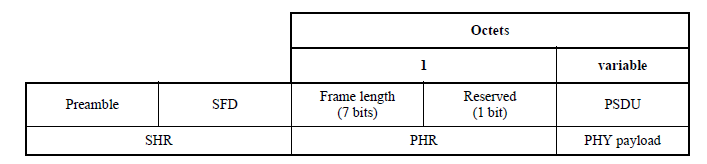
The 802.15.4 O-QPSK BPSK signal is generated on a PPDU (physical protocol data unit) basis. A PPDU includes the SHR, PHR and PSDU parts as defined in the 802.15.4 specification and when configured, an idle interval. A PPDU is the same as a frame so the two terms are interchangeable. The software uses the term frame. The figure below shows the frame structure. A waveform can include one or more frames depending on the settings. When there are multiple frames, an idle interval may be set between them. When the idle interval is set to zero (no idle interval), a continuous non-bursted signal is generated.
The SHR part uses fixed values that are generated by the software.
The PHR is also generated. The value for this property is set by the software's PSDU properties Data Length (Octets) and MAC FCS also located in the same node.
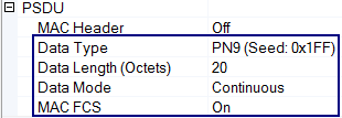
The PHY payload part, PSDU consists of fields that are configurable with the software. The following figure shows these fields.
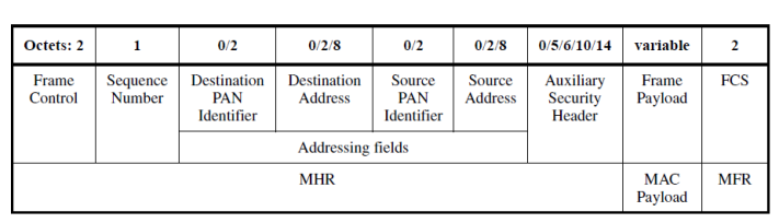
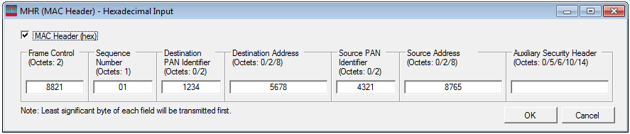
The MHR (MAC Header) field uses a dialog box in the software to figure its values. Use the MAC Header (hex) check box to either turn the header on or off. The fields are only configurable with the header on (check box checked)
The remaining fields of the PSDU that includes the MAC payload and MFR, are configured using ![]() cell properties.
cell properties.
The marker source selection RF Blanking Control is unique in that it performs two functions during waveform playback, ALC hold and RF Blanking. In order to perform ALC hold, there is a period where sampling occurs during a frame transmission. This is done so the instrument knows at what level to hold the ALC circuitry during the RF blanking. The sampling period begins on the second half of the first symbol of the frame and ends on the first half of the last symbol. The instrument then holds its ALC level prior to the start of RF blanking and ends one Tc into the next frame. In a multi-frame signal, this process is repeated for each frame and idle interval. The following figure shows how the software implements the RF Blanking marker selection.
![]()
For the RF Blanking selection, the Idle Interval determines whether the actual RF blanking occurs. When Idle Interval is set to zero, there is no RF blanking during waveform playback, only the ALC hold sampling occurs.